Manufacturing
November 18 2026
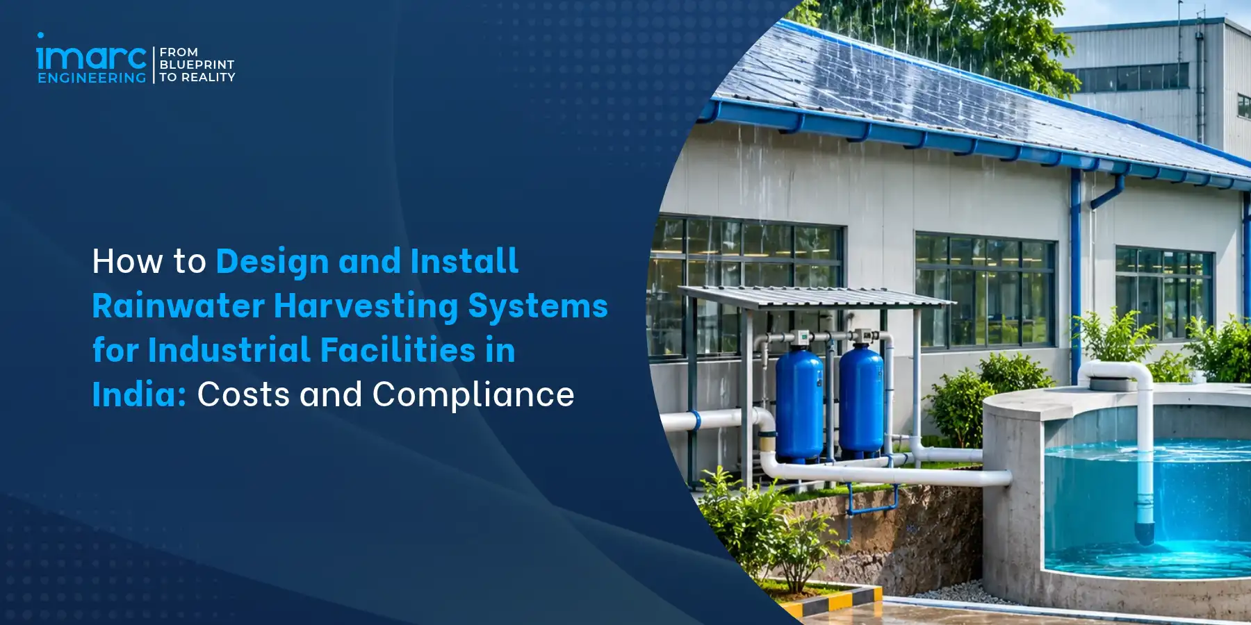
How to Design and Install Rainwater Harvesting Systems for Industrial Facilities in India: Costs and Compliance
Introduction
Industrial water security in India is no longer a utilities afterthought. Manufacturing plants, warehouses and commercial campuses draw heavily on borewells and municipal supply, and in many industrial belts groundwater regulators, pollution control boards and local bodies expect facilities to demonstrate water conservation. Industrial rainwater harvesting system design sits at the intersection of hydrology, civil engineering, filtration and regulation. A system sized from a catalogue or a rule of thumb typically either overflows during peak storms or sits empty for most of the year.
For investors, project sponsors and plant managers, the central questions are practical: how much water a roof can realistically yield, whether to store, recharge or combine both, what equipment is needed, what it costs, and which approvals apply.
Scope of this Guide
This guide answers one question: how can industrial facilities in India design, install and maintain rainwater harvesting systems that meet their water management requirements while considering engineering costs, site conditions and regulatory compliance? It covers rooftop and surface-runoff harvesting for factories, warehouses and commercial establishments, including storage, groundwater recharge and hybrid configurations, from site assessment through commissioning. It does not treat residential installations, and it presents rainwater harvesting as a project type for evaluation rather than as an established standalone IMARC Engineering service line.
Table of Contents
- Introduction
- Industrial Rainwater Harvesting System Design in India
- Types of Industrial Rainwater Harvesting Systems: Storage, Recharge and Hybrid Design
- Key Factors in Industrial Rainwater Harvesting System Design
- Rainwater Harvesting Capacity Calculation for Industrial System Design
- Components and Equipment for Industrial Rainwater Harvesting System Design and Installation
- Step-by-Step Industrial Rainwater Harvesting System Design Process and Integration with Existing Infrastructure
- Industrial Rainwater Harvesting System Installation Cost in India and Project Economics
- Regulatory Compliance, Maintenance and Checklist for Industrial Rainwater Harvesting System Design
- Conclusion
1. Industrial Rainwater Harvesting System Design in India
Industrial rainwater harvesting system design matters because large roofs, paved yards and concentrated water demand make factories one of the more productive settings for harvesting.
1.1 Industrial Water Conservation and Why Facilities Harvest Rainwater
Manufacturing plants consume water for cooling tower make-up, boiler feed, washing, process dilution, dust suppression, landscaping and sanitation. Some applications can use non-potable water, making harvested rainwater a potential supplementary source. However, cooling towers, boilers and manufacturing processes may require additional treatment depending on their water quality requirements.
Large, uncluttered roofs of pre-engineered buildings and warehouses collect substantial volumes during short monsoon bursts. Impermeable yards and internal roads also generate runoff that otherwise leaves the site through stormwater drains. Rainwater harvesting can reduce dependence on borewell and tanker supplies, lower stormwater discharge and support groundwater recharge where site conditions and applicable regulations permit.
1.2 Where Industrial Rainwater Harvesting Applies
Applications include manufacturing plants with extensive roof area, logistics parks and warehouses, pharmaceutical and electronics campuses with non-process water uses, automotive plants with large paint-shop and washing demand, food processing units, and commercial or institutional campuses within industrial estates. Suitability depends on the roof material, the quality of runoff, the share of water demand that tolerates untreated or lightly treated water, and whether the aquifer beneath the site is a viable recharge target.
1.3 Water Management and Project Planning Context
Rainwater harvesting should be planned inside the plant water balance, not as an add-on. A water balance lists sources (municipal, borewell, tanker, recycled effluent), uses (process, utilities, domestic) and losses, and shows how much harvested water the plant can actually absorb. Early planning also avoids a common error: laying out roof drainage and yard grading during civil design without allowing for collection points, which forces expensive retrofitting later. Feasibility work on cost, siting and approvals is where IMARC Engineering's services apply to this type of evaluation.
1.4 The Cost of Poor Planning
Oversized tanks are built for annual rainfall totals rather than for the dry-spell demand they will actually serve, leaving capital idle. Recharge structures are placed on impermeable or contaminated ground, so they clog or threaten groundwater quality. And systems are commissioned with no maintenance plan, so first-flush devices and filters foul within a season and the installation is bypassed. Each of these is a design-stage decision rather than a construction defect.
2. Types of Industrial Rainwater Harvesting Systems: Storage, Recharge and Hybrid Design
The choice between storage, recharge and hybrid configurations is the first major decision in industrial rainwater harvesting system design, and it determines civil scope, equipment and approvals.
2.1 Rooftop Collection with Storage and Reuse
Roof runoff is conveyed through gutters and downpipes, passes a first-flush diverter and filter, and is held in an underground or above-ground tank for later use. Tanks are typically reinforced concrete, masonry, or prefabricated HDPE or FRP units. This route delivers usable water on site, offsets borewell or tanker draw, and suits plants with steady non-potable demand. Its limit is tank volume: storage cannot economically capture a full monsoon peak, so surplus must overflow to recharge or drainage.
2.2 Surface Runoff Harvesting
Paved yards, internal roads and open areas generate surface runoff that may contain oil, grease, rubber particles, dust and chemical residues. Industrial runoff requires appropriate collection, segregation and treatment measures, such as silt traps, oil and grease separators, and settling or detention ponds, depending on contamination risks.
Surface runoff may provide additional harvesting potential, but its suitability for reuse or groundwater recharge depends on water quality, site conditions and applicable regulations. Runoff from contaminated industrial areas should not be directed into groundwater recharge structures without appropriate assessment and treatment.
2.3 Groundwater Recharge Systems
Recharge structures return filtered runoff to the aquifer. Options include recharge pits filled with graded media, recharge trenches along building edges, injection or recharge wells passing through low-permeability layers to a permeable zone, and percolation tanks or ponds where land permits. Selection depends on soil permeability, depth to water table, aquifer type and the quality of inflow. Recharge needs no stored volume but does need a hydrogeological assessment and protection of groundwater from contaminated runoff.
2.4 Hybrid Systems and Comparison
A hybrid system stores the first portion of each storm for reuse and sends overflow to recharge, combining supply benefit with aquifer benefit and limiting tank size. Comparative characteristics are summarized below.
| Parameter | Storage and Reuse | Groundwater Recharge | Hybrid |
|---|---|---|---|
| Primary benefit | On-site supply offset | Aquifer replenishment | Both |
| Key constraint | Tank volume and demand | Soil, water table, runoff quality | Higher design complexity |
| Site dependence | Moderate | High | Moderate to high |
| Equipment intensity | Tanks, pumps, filters | Pits, wells, filter media | Combined |
| Maintenance focus | Filters, tank cleaning | Silt removal, clogging | Both |
| Typical fit | High non-potable demand | Water-stressed aquifers | Sites with suitable reuse demand and technically feasible groundwater recharge conditions |
The weighting among these options is project-specific and should follow the water balance and hydrogeological findings.
3. Key Factors in Industrial Rainwater Harvesting System Design
Industrial rainwater harvesting system design depends on a small set of site variables, each of which must be measured rather than assumed.
3.1 Rainfall Data and Intensity
Design uses long-term rainfall records from the India Meteorological Department or the nearest reliable station, covering annual totals, monthly distribution, number of rainy days and short-duration intensity. Annual totals govern potential yield; intensity governs gutter, downpipe and drain sizing because a short, heavy burst, not the annual average, sets peak flow. Rainfall in India is strongly seasonal, so the dry-season gap determines how much storage is useful.
3.2 Catchment Area and Surface Type
Catchment area is the horizontal projected area draining to collection points, not the sloped roof surface. Roof material affects both runoff coefficient and quality: metal sheeting and concrete shed water efficiently, while bituminous or asbestos-containing surfaces raise quality and handling concerns. Yards and roads add catchment but also contamination, and each surface type should be mapped separately.
3.3 Water Demand and Water Balance
A water balance assessment identifies which uses can accept harvested water and at what volume and timing. Cooling tower make-up, washing, flushing, gardening and fire reserve top-up are common targets. Demand that is continuous through the dry season makes storage valuable; seasonal or low demand shifts the design toward recharge.
3.4 Drainage, Soil and Groundwater Conditions
Existing industrial drainage layout, ground levels and discharge points govern collection routes. Soil permeability tests, such as infiltration or percolation tests, and borehole logs indicate whether recharge is feasible, while depth to water table and seasonal fluctuation define recharge well depth and clearance. Where the water table is shallow or the soil is clayey, recharge capacity is limited and storage takes a larger share of the design. A hydrogeological assessment should confirm these conditions before recharge structures are specified.
4. Rainwater Harvesting Capacity Calculation for Industrial System Design
Rainwater harvesting capacity calculation separates three quantities that are often confused: annual collection potential, storage capacity and usable yield.
4.1 Annual Collection Potential
Collection potential is the theoretical volume the catchment can deliver: catchment area multiplied by rainfall depth multiplied by a runoff coefficient. The runoff coefficient represents losses from evaporation, splash, wetting and leakage, and varies with surface type and condition. Because published coefficients differ by source and surface, the value used should be stated, justified for the actual roof material and confirmed by the designer.
4.2 Storage Sizing Versus Usable Yield
Storage capacity is the tank volume; usable yield is the water actually delivered to users after first-flush loss, overflow and dry-spell shortfalls. Because rainfall is seasonal, a tank sized to the annual potential overflows repeatedly and holds capital in unused volume. Practical sizing links tank volume to the demand that must be covered between rain events, using daily or monthly water balance simulation rather than the annual total alone.
4.3 Rainfall Distribution and Recharge Feasibility
Recharge sizing is governed by the volume of a design storm and the infiltration rate of the soil, not by annual rainfall. A recharge pit or trench must absorb the runoff from a chosen design storm within an acceptable drain-down period, which depends on the measured permeability. Where infiltration is slow, multiple structures or a larger footprint are needed, or the design shifts toward storage.
4.4 Illustrative Calculation Example
The following is a single illustrative case, not a benchmark. Assumptions: a manufacturing plant with 10,000 square meters of roof catchment; annual rainfall of 800 mm; a runoff coefficient of 0.80; first-flush loss neglected for simplicity; non-potable demand of 20 cubic meters per day; and a design storm of 50 mm for recharge sizing.
Annual collection potential = 10,000 m² × 0.800 m × 0.80 = 6,400 cubic meters per year. This is potential, not delivered supply.
Demand check: 20 cubic meters (about twice the volume of a storage unit) per day equals about 7,300 cubic meters per year, so rainwater alone cannot meet this demand, and in dry months it provides nothing.
Storage logic: Storage capacity should be determined through a site-specific water balance analysis rather than a fixed dry-spell assumption. The assessment should consider rainfall distribution, daily water demand, first-flush losses, overflow, usable yield and the duration between rainfall events. The final tank capacity should also account for freeboard and sediment allowance.
For illustration, supplying 20 cubic meters per day over a 10-day period would require 200 cubic meters of usable stored water. This is a demand-based calculation, not a recommended tank capacity. Final storage sizing should use a site-specific water balance covering rainfall distribution, collection losses, overflow, usable yield and periods between rainfall events.
Design storm volume for recharge: 10,000 m² × 0.050 m × 0.80 = 400 cubic meters per event. After storage absorbs part of this, the remainder must be infiltrated or drained, and recharge structures are sized from measured soil permeability and the allowable drain-down time. All figures are illustrative, and the actual design must use site rainfall data, measured coefficients and hydrogeological results (Figures are indicative in nature, may vary).
5. Components and Equipment for Industrial Rainwater Harvesting System Design and Installation
Rainwater harvesting system components fall into collection, treatment, storage, distribution and recharge groups, each with specification points that affect performance.
5.1 Collection and Conveyance
Gutters and downpipes are sized for design rainfall intensity and roof area, with outlets, expansion allowance and overflow routes planned. Materials include galvanized or pre-coated steel, aluminium and uPVC, chosen for corrosion resistance and compatibility with the roof. Underground piping uses uPVC, HDPE or RCC pipe with defined gradients, inspection chambers and silt-trapping manholes at junctions.
5.2 First-Flush Diversion and Filtration
A first-flush diverter discards the initial runoff that carries accumulated dust, bird droppings and residues; the diverted volume is set from the catchment area and local conditions rather than from a universal figure. Downstream filtration typically combines screens or leaf traps, settling, and media filters such as sand and gravel or cartridge filters, with disinfection added if the water reaches sensitive uses. Filtration is selected against the intended end use and the measured water quality.
5.3 Storage Tanks, Pumps and Valves
Storage options include RCC underground tanks, masonry tanks and prefabricated HDPE or FRP tanks, with inlet baffles to limit sediment disturbance, overflow to recharge or drainage, ventilation, manholes and a sump for desludging. Pumps are selected for flow and head against the reuse network, with float or level controls, non-return and isolation valves, and bypass arrangements. Level instrumentation supports monitoring and automated changeover to alternative supply.
5.4 Recharge Structures
Recharge pits and trenches use graded filter layers, commonly coarse aggregate, gravel and sand, within a lined or perforated chamber, with silt chambers upstream to protect them from clogging. Recharge wells reach permeable strata through casing and filter packs, and require careful siting relative to groundwater use and contamination sources. Protective measures such as oil separators for yard runoff and non-return arrangements prevent polluted water reaching the aquifer.
6. Step-by-Step Industrial Rainwater Harvesting System Design Process and Integration with Existing Infrastructure
The design sequence converts site data into drawings and specifications, and the same data determines how a system connects to existing factory infrastructure.
6.1 Site Survey, Water Balance and Technology Selection
The design begins with a survey of roofs, levels, drains and open areas, rainfall data collection, soil and groundwater investigation, and water demand mapping. The water balance then tests storage, recharge and hybrid options against demand, and technology selection is documented with the reasoning so regulators and lenders can follow it.
6.2 Hydraulic Design, Drawings and Specifications
Hydraulic calculations size gutters, downpipes, collection drains and overflow paths for design intensity, and size tanks and recharge structures from the water balance and design storm. Outputs include catchment plans, plumbing and drainage layouts, tank and recharge details, pump schedules, equipment specifications and a bill of quantities.
6.3 Installation Sequence and Commissioning
Installation proceeds through site preparation and setting out, excavation and civil works for tanks and recharge structures, installation of gutters and piping, filter and diverter installation, tank placement, pumps and controls, and recharge media filling. Commissioning includes hydrostatic or leak testing of tanks and pipes, flow checks with simulated rainfall or flushing, verification of overflow routing, calibration of level controls, and a water quality check before reuse. As-built drawings and operating instructions are handed over.
6.4 Integration with Factory Roofs, Drainage and Utility Networks
Brownfield integration starts with checking roof loads and drainage outlets on existing buildings, tapping downpipes into a collection header without compromising fire-fighting or stormwater capacity, and routing overflow back to the existing drain. Harvested water can connect to cooling tower make-up, utility water tanks or a treatment system, with backflow prevention and clear labeling to avoid cross-connection with potable supply. In operating plants, work is scheduled around production, and site-specific constraints such as underground services and congested yards often decide the achievable layout.
7. Industrial Rainwater Harvesting System Installation Cost in India and Project Economics
Industrial rainwater harvesting system cost depends on configuration, civil scope and site conditions, and should be built up from quotations rather than assumed from a benchmark.
7.1 Cost Drivers
The main cost drivers are catchment size, whether storage or recharge dominates, excavation and soil conditions, tank material and volume, depth and number of recharge structures, filtration and treatment level, pumping and controls, and the extent of brownfield modification. Sites with rock, high water tables or congested underground services cost more per unit of capacity than open greenfield plots.
7.2 CAPEX Components
Capital expenditure typically includes site survey and hydrogeological assessment, engineering and design, civil works for tanks and recharge structures, collection piping and drains, first-flush devices and filters, tanks, pumps and controls, electrical and instrumentation, commissioning and contingency. Land is normally already owned and is excluded.
7.3 OPEX Planning
Operating costs include filter media replacement and cleaning, tank desludging, pump power, periodic water quality testing, recharge structure maintenance, inspection labor and monitoring. These are generally small relative to CAPEX but should be budgeted explicitly so that maintenance is not deferred.
7.4 Project Economics
Capital investment in an industrial rainwater harvesting system depends on the catchment area, storage and recharge configuration, site conditions, civil construction requirements and equipment specifications. Instead of applying a generic investment benchmark, project costs should be developed using site assessments, engineering estimates and vendor quotations.
The main CAPEX components include:
- Land and Civil Works: Excavation, foundations, storage tank construction, recharge pits, trenches and drainage infrastructure.
- Plant and Machinery: Storage tanks, filtration systems, first-flush diverters, pumps, valves and associated equipment.
- Utilities and Installation: Collection piping, electrical connections, instrumentation, controls and installation works.
- Engineering and Pre-operative Expenses: Site surveys, hydrogeological investigations, hydraulic design, technical consultancy and applicable approvals.
- Contingency: Provision for unforeseen civil works, site-specific modifications and installation requirements.
Operating expenditure should also be evaluated, including pump electricity, filter replacement, tank cleaning, periodic water quality testing and maintenance of recharge structures. The final project economics should compare capital and operating costs against potential savings from reduced dependence on external water sources.
8. Regulatory Compliance, Maintenance and Checklist for Industrial Rainwater Harvesting System Design
Regulatory obligations, maintenance discipline and a structured checklist determine whether a designed system remains compliant and productive.
8.1 Regulatory Requirements and Compliance
Regulatory requirements for industrial rainwater harvesting in India depend on the project location, groundwater usage, site classification and applicable local regulations. The Central Ground Water Authority (CGWA) regulates groundwater extraction through applicable guidelines and no-objection certificate requirements. Industrial facilities using groundwater must assess the relevant conditions, including any water conservation or recharge obligations attached to their approvals.
State groundwater authorities and applicable state legislation may impose additional requirements. Municipal building bye-laws, development authority regulations and industrial area guidelines may also prescribe rainwater harvesting provisions for specified categories of buildings or plots.
Projects should additionally review applicable environmental clearance conditions, State Pollution Control Board consents and site-specific requirements. Facilities proposing groundwater recharge must assess water quality and comply with relevant groundwater protection conditions.
Rainwater harvesting is not a universal regulatory requirement for every industrial facility. Before finalising the design, project developers should verify the latest CGWA guidelines, applicable state groundwater regulations, municipal building rules and environmental conditions with the relevant authorities.
8.2 Water Quality, Contamination and Groundwater Protection
Industrial runoff can carry oil, solvents, heavy metals, fertilizer or process residues, especially from yards, loading bays and chemical storage areas. Roof runoff is generally cleaner but still carries dust and atmospheric deposits. Design should segregate contaminated areas from the collection network, use oil and grease separators and silt traps, and prevent runoff from hazardous storage zones from entering recharge structures. Recharge water quality should be tested against applicable groundwater protection criteria, and recharge should be avoided where contamination cannot be excluded.
8.3 Maintenance and Performance Monitoring
Maintenance frequency depends on rainfall, dust load, surrounding vegetation and design, but a practical programme inspects gutters, screens and first-flush devices before each monsoon and after major storms, cleans or replaces filter media as water quality and flow indicate, desilts tanks and silt chambers periodically, and checks recharge structures for clogging by monitoring drain-down time. Water quality testing, pump servicing and level sensor calibration complete the routine. Monitoring metrics may include volume harvested, volume reused, recharge drain-down performance and quality parameters, recorded against design assumptions.
8.4 Common Challenges, Consultant Support and Design Checklist
Frequent problems include undersized or oversized storage, contaminated inflow, drainage conflicts, clogged recharge media, groundwater limitations and lapsed maintenance. Engineering consultants support feasibility, site and hydrogeological coordination, hydraulic design, CAPEX planning, regulatory assessment and supervision, though rainwater harvesting design and installation should be treated as a project type under evaluation rather than a confirmed standalone IMARC Engineering service.
Design and Installation Checklist:
- Technical: Rainfall records, catchment survey, runoff coefficient, water balance, design storm, soil permeability, water table data.
- Design: Storage, recharge or hybrid selected with documented basis; hydraulic calculations, drawings and equipment specifications completed.
- Financial: CAPEX and OPEX built from quotations; sensitivity to civil and soil conditions tested.
- Regulatory: CGWA, state groundwater, municipal and environmental requirements confirmed for the project.
- Installation: Civil works, piping, filtration, tanks and recharge structures built to drawings; leak and flow tests done.
- Operation: Maintenance schedule, monitoring plan, quality testing and responsibilities assigned.
Conclusion
A reliable industrial rainwater harvesting system must be based on site-specific rainfall, catchment, water demand and soil conditions. These factors determine whether storage, groundwater recharge or a hybrid system is most suitable, along with the required infrastructure, costs and approvals.
Effective project planning requires reliable site data, appropriate infrastructure selection, groundwater protection and compliance with applicable regulations. Feasibility assessment, utilities planning, plant layout and capital expenditure evaluation help project developers determine the technical and commercial viability of rainwater harvesting infrastructure within their broader industrial water management strategy.
PURSUING AN INDUSTRIAL RAINWATER HARVESTING PROJECT IN INDIA?
IMARC Engineering's existing consulting capabilities in feasibility assessment, plant layout, utilities planning, regulatory assessment and CAPEX planning may support the initial evaluation of industrial water management projects. Any rainwater harvesting-specific design, installation or commissioning scope would need to be confirmed separately.
→ Schedule an industrial water management project feasibility consultation with an IMARC specialist
Frequently Asked Questions
Start with rainfall records, catchment survey, water demand mapping and a soil and groundwater assessment. Build a water balance, choose storage, recharge or a hybrid, then size gutters, tanks and recharge structures from design intensity and design storm. Finish with drawings, equipment specifications, installation, commissioning and a maintenance plan.
The main types are rooftop collection with storage and reuse, surface runoff harvesting with detention and treatment, groundwater recharge through pits, trenches and recharge wells, and hybrid systems combining storage with recharge. Selection depends on water demand, soil permeability, groundwater conditions and runoff quality.
Annual collection potential equals catchment area multiplied by rainfall depth multiplied by a runoff coefficient. This is potential, not usable supply. Storage is then sized from demand between rain events and usable yield is reduced by first-flush loss and overflow. Recharge is sized from design storm volume and measured soil permeability.
Core equipment includes gutters and downpipes, collection piping and silt-trapping chambers, a first-flush diverter, screens and media or cartridge filters, storage tanks, pumps with level controls and valves, and recharge pits, trenches or wells with filter media. Oil separators are added where yard runoff is harvested.
The cost depends on catchment area, storage and recharge requirements, soil conditions, civil works, filtration systems and installation scope. Major investment components include civil construction, tanks, pumps, piping, filtration equipment, engineering and commissioning. Actual project costs should be established through site assessments and vendor quotations.
Storage tank capacity is determined through a site-specific water balance analysis rather than annual rainfall alone. The calculation considers rainfall distribution, daily water demand, first-flush losses, overflow and the duration between rainfall events. Final capacity should also account for freeboard and sediment allowance.
Storage holds harvested water in tanks for later on-site use, offsetting other supply. Recharge returns filtered runoff to the aquifer through pits, trenches or wells and creates no usable stored volume. Storage is limited by tank size and demand; recharge is limited by soil permeability and groundwater protection needs.
Yes, subject to site constraints. Retrofits require checking roof loads, tapping existing downpipes into a collection header, routing overflow to current drains, protecting underground services and avoiding cross-connection with potable supply. Work is usually phased around production, and congested yards may limit tank or recharge locations.
Requirements depend on location, groundwater category and permit conditions, and must be confirmed with the relevant authority. Technically, recharge needs suitable soil permeability, adequate clearance above the water table, pre-filtration and silt control, and protection from contaminated runoff so that recharged water does not degrade groundwater quality.
It depends on the jurisdiction. Some state groundwater rules, municipal or industrial-area bye-laws and CGWA no-objection conditions may require harvesting or recharge, often linked to plot size or groundwater withdrawal. Current requirements should be verified for the specific state, local body and project before design.
Recent Post




Trusted by Industry Leaders
We partner with global enterprises and ambitious businesses across sectors to deliver operational excellence, strategic insights, and sustainable growth through integrated solutions.












Success in Their Words
Real feedback from clients across industries. Discover how our solutions delivered measurable impact and operational excellence.

I wanted to express my sincere appreciation for your efforts in handling this matter. Your dedication and commitment have been truly commendable, and it is evident that you have put in tremendous hard work and expertise into resolving the issues at hand. We are greatly interested in continuing our collaboration with you in the future, as your professionalism and reliability have made you a trusted partner. Thank you once again for your invaluable contribution. We look forward to strengthening our partnership ahead.

It has been a pleasure working with the IMARC team. The insights provided were structured, clear, and highly valuable, helping us strengthen both our technical and financial planning with confidence. We deeply appreciate the team’s professionalism, responsiveness, and attention to detail throughout the engagement. Every requirement was well understood and effectively incorporated, resulting in a comprehensive and actionable output. Overall, our experience has been excellent, and I would gladly recommend IMARC to organizations seeking a reliable research partner.

Your service is truly exceptional. Working with the IMARC team has been a seamless and professional experience. The clarity of communication, responsiveness to queries, and consistent support at every stage made the entire engagement highly efficient. The insights shared were well-structured, practical, and perfectly aligned with our requirements, helping us make informed decisions with confidence. Overall, the dedication and professionalism demonstrated by your team stand out, and I would be glad to recommend IMARC as a reliable and trustworthy research partner.

IMARC did an outstanding job in preparing our study. They were punctual, precise, and consistently responsive throughout the entire process. The team delivered all the data we required in a clear, well-organized, and highly professional format. Their strong attention to detail, combined with their ability to meet every deadline without compromising quality, truly set them apart. Overall, their reliability and commitment made them an exceptional partner for our project, and we would gladly work with them again in the future.

IMARC made the whole process incredibly easy from start to finish. Everyone I interacted with via email was polite, professional, and straightforward to deal with, always keeping their promises regarding delivery timelines and remaining consistently solutions-focused. From my very first contact, I appreciated the professionalism and support shown by the entire IMARC team. I highly recommend IMARC to anyone seeking timely, affordable, and reliable information or advice. My experience with IMARC was excellent, and I truly cannot fault any aspect of it.

I’d like to express my sincere gratitude for the excellent work you accomplished with the study. Your ability to quickly understand our requirements and deliver high-quality results under tight timelines truly reflects your expertise, exceptional work ethic, and unwavering commitment to your customer’s success. The professionalism and responsiveness you demonstrated throughout the process made a significant difference. Our entire team and company are incredibly thankful for your dedication, reliability, and support. Once again, thank you for your outstanding contribution.