Manufacturing
November 16 2026
How to Set Up a CBG Storage and Refilling Facility in India: Cascade Systems, Transportation, and Investment
Introduction
A CBG storage and transportation facility represents a downstream gas-handling asset distinct from a biogas production plant. While a production plant processes feedstock through anaerobic digestion and upgrades raw biogas into biomethane, a downstream facility receives specification-compliant gas, compresses it where required, stores it in certified high-pressure vessels, transports it through cascade-mounted vehicles and supplies it to vehicle or industrial customers. These facilities differ in their processes, capital requirements, operational risks and regulatory requirements.
Effective project planning must account for throughput, delivery distance, operating pressure, storage utilization and the reliability of gas supply arrangements. Cascade capacity should be determined through a logistics and trip-frequency assessment, while compressor specifications must reflect the available inlet pressure and required delivery conditions. Inadequate planning can result in underutilized equipment, operational bottlenecks and higher project costs.
Scope of this Guide
This guide answers one question: how can investors establish a CBG storage, transportation and refilling facility in India, select appropriate compression and storage infrastructure, estimate investment requirements, prepare a DPR, and meet applicable safety and regulatory standards? It covers gas receiving, quality verification, compression where required, stationery and mobile cascade storage, transportation, dispensing, safety systems and approvals. Anaerobic digestion, feedstock sourcing and biogas purification are outside its scope.
Table of Contents
- Introduction
- Why CBG Storage and Transportation Facility in India Matters for Investors in 2026
- CBG Storage and Transportation Facility in India: Facility Types and Infrastructure Models
- How to Set Up a CBG Storage and Transportation Facility in India: Roadmap, Storage Technologies and Transportation
- CBG Refilling Station Design, Operating Process and Machinery in a CBG Storage and Transportation Facility in India
- Land, Plant Layout and Utility Requirements for a CBG Storage and Transportation Facility in India
- CBG Storage and Transportation Facility in India: Cost, CAPEX, OPEX and Financial Feasibility
- Detailed Project Report (DPR) for a CBG Storage and Transportation Facility in India
- Regulatory Approvals, Safety Compliance and Project Challenges for a CBG Storage and Transportation Facility in India
- Conclusion
1. Why CBG Storage and Transportation Facility in India Matters for Investors in 2026
Four conditions make downstream CBG infrastructure strategically significant, and each one changes the configuration an investor should fund.
1.1 CBG Value Chain and the Downstream Gap
The CBG value chain runs from feedstock collection through anaerobic digestion and upgrading to biomethane, then compression, storage, transport and dispensing. Many production plants are located in agricultural or waste-generating belts that are distant from the vehicle fleets, industrial burners and city gas networks that consume the gas. The gap between a producer's gate and a customer's tank is filled by compression, cascade logistics and refilling infrastructure. This guide treats that gap as the investable asset.
1.2 Policy Framework and Offtake Context
The Petroleum and Natural Gas Regulatory Board (PNGRB) regulates specified downstream natural gas activities, including authorised city gas distribution networks and applicable pipeline infrastructure. PNGRB requirements for a CBG facility depend on its activities and configuration. Pipeline injection, automotive fuel dispensing and standalone storage or transportation may fall under different regulatory requirements. Investors should establish the applicable framework based on the proposed business model, location and operating arrangements.
1.3 Industrial Applications and Distribution Opportunities
CBG can serve CNG-compatible vehicle fleets, industrial thermal applications where pipeline gas is unavailable, and captive or institutional users. Mobile cascades allow delivery to customers without a pipeline connection, which is the commercial rationale for transportation infrastructure. Revenue depends on the supply arrangement, the delivery model and the customer mix, which are examined in Sections 6 and 7.
1.4 The Cost of Poor Planning
Inadequate logistics planning can result in vehicle idling at loading points due to insufficient trip-frequency and turnaround assessments. Selecting compressors without clearly defined inlet pressure and gas specifications can lead to inefficient or unreliable operations. Similarly, treating the project as a conventional production facility during permitting and budgeting may result in incorrect equipment specifications, incomplete approvals planning and an inaccurate investment assessment. Key factors such as gas losses, plant utilisation and transportation economics must be evaluated during project planning.
2. CBG Storage and Transportation Facility in India: Facility Types and Infrastructure Models
Facility type decides the equipment list, regulatory scope and capital requirement before capacity is fixed.
2.1 Raw Biogas, Biomethane and Compressed Biogas: Terminology
Raw biogas is the digester output, typically a mixture of methane and carbon dioxide with trace hydrogen sulphide and moisture, and is usually stored at low pressure in gas holders. Upgraded biomethane is biogas processed to meet the applicable biomethane quality specification. In India, IS 16087:2025 specifies the quality requirements for biogas (biomethane), subject to the applicable end-use and regulatory requirements.
Compressed biogas, or CBG, is biomethane compressed to high pressure for storage and transport, commonly in the range associated with CNG cascades. Biogas storage is therefore a low-pressure buffering function inside a production plant, whereas CBG storage is a high-pressure, certified-vessel function in downstream infrastructure, governed by different codes and approvals.
2.2 Facility Configurations
Four configurations are common. A producer-side compression and cascade-filling station sits at the CBG plant and loads mobile cascades. A mother station receives gas, compresses it and fills transport cascades for a defined hinterland. A daughter or refilling station receives gas from mobile cascades and dispenses to vehicles. An integrated facility combines compression, stationary storage, cascade loading and dispensing on one site. Selection depends on supply arrangement, delivery distance and the customer base.
2.3 Infrastructure Models Compared
The infrastructure model is chosen on supply security, capital intensity and operating model, as the comparison shows.
| Model | Function | Gas Source | Capital Intensity | Key Dependency |
|---|---|---|---|---|
| Producer-side compression station | Compress and fill mobile cascades at plant | Own CBG plant | Moderate | Plant output stability |
| Mother station | Compress and load transport cascades | Pipeline or producer supply | Higher | Throughput and compressor utilisation |
| Daughter refilling station | Receive cascades, dispense to vehicles | Mobile cascades | Lower | Cascade delivery reliability |
| Integrated facility | Compression, storage, loading, dispensing | Mixed | Highest | Combined throughput and permits |
(Figures are indicative in nature, may vary.)
2.4 Plant Sections
| Section | Function | Key Equipment |
|---|---|---|
| Gas receiving | Receive and meter incoming CBG | Inlet filter, flow meter, pressure regulator |
| Quality verification | Confirm gas specification | Online analyser, moisture meter, sampling point |
| Gas drying | Remove residual moisture where required | Dryer, coalescing filter |
| Compression | Raise gas to storage pressure | Reciprocating compressor, cooler, buffer vessel |
| Stationary storage | Hold gas at high pressure | Certified cylinder cascade, priority panel |
| Mobile cascade loading | Fill transport cascades | Filling posts, hoses, breakaway couplings |
| Dispensing | Fill vehicles | Dispenser, mass flow meter, nozzles |
| Safety systems | Detect and isolate hazards | Gas detectors, ESD, fire protection |
| Utilities | Power and control | Transformer, DG set, instrument air, SCADA |
| Vent and drain handling | Manage blowdown and condensate | Vent stack, condensate trap |
3. How to Set Up a CBG Storage and Transportation Facility in India: Roadmap, Storage Technologies and Transportation
A structured roadmap links commercial, technical and regulatory decisions, and storage and transport technologies are selected within it.
3.1 Step-by-Step Setup Roadmap
The sequence is: define the business model and customer base; secure indicative gas supply terms; carry out feasibility and capacity planning; select the site and confirm land use, access and hazardous-area suitability; complete process design and equipment specification; prepare the DPR and financial model; obtain approvals including PESO, fire and pollution-board consents where applicable; procure and install equipment; commission with leak, pressure and functional testing; and ramp up operations. Approvals and procurement can run in parallel where dependencies allow, and their duration depends on the authority, location and project scope.
3.2 Stationary Cascade Storage
A stationary cascade consists of high-pressure cylinders or vessels that may be arranged in low-, medium- and high-pressure banks. A priority or sequencing system manages gas delivery according to available bank pressures, vehicle pressure and the station's control strategy to improve storage utilisation and filling performance.
Vessels must be certified to the applicable pressure-vessel and gas-cylinder requirements, and their design pressure, water capacity and test regime are confirmed with PESO. Storage capacity is sized from peak dispensing demand, compressor capacity and the desired buffer, not from a standard module count.
3.3 Mobile Cascades and Tube Trailers
A mobile cascade is a set of cylinders or tubes mounted on a trailer or truck chassis and used to move gas between a filling point and a delivery point. Capacity per trailer depends on the cylinder configuration, the working pressure approved for the vessels and the road-vehicle weight limits, so it is a vendor- and approval-specific figure. The delivered quantity is also limited by the residual pressure left in the cascade at the customer, which is why trailer design, delivery pressure and the customer's receiving system must be matched.
3.4 CBG Transportation and Distribution Systems
Transportation economics are driven by trailer payload, one-way distance, loading and unloading time, turnaround and trip frequency. Loading uses filling posts with hoses and breakaway couplings, and unloading uses a decanting arrangement at the receiving station or customer. Transport safety depends on vessel certification, valve protection, restraint of the cascade, driver training and emergency response arrangements. A logistics model should compute the number of trailers required for a target daily delivery, since a single trailer's idle time during loading and unloading directly reduces its effective capacity.
4. CBG Refilling Station Design, Operating Process and Machinery in a CBG Storage and Transportation Facility in India
The station converts received gas into dispensed fuel through a defined process sequence, and machinery is specified against that sequence.
4.1 Gas Receiving and Quality Verification
Gas arrives by pipeline, from a producer's compressor or from a mobile cascade. Receiving includes inlet isolation, filtration, pressure regulation and metering. Quality verification confirms that the gas meets the specification agreed with the supplier and applicable standards, including methane content, moisture, hydrogen sulphide and other contaminants. Gas quality should be verified against the applicable requirements of IS 16087:2025 and the relevant supply or offtake agreement. Testing should cover the specified parameters, including methane content, moisture, hydrogen sulphide and other relevant contaminants.
4.2 Compression, Storage and Dispensings
Where inlet pressure is below storage pressure, a multi-stage reciprocating compressor with inter-stage cooling raises the gas to cascade pressure. Compressed gas passes to the priority panel and stationary cascade. Dispensers draw from the cascade through pressure regulation, a mass flow meter and a vehicle-rated nozzle, with temperature and pressure compensation so that fills are metered accurately.
Where a station receives CBG through mobile cascades, gas may be dispensed through pressure-based decanting. However, a booster compressor or other suitable arrangement may be required to maintain dispensing pressure, improve cascade utilisation or achieve the planned throughput.
Illustrative CBG Storage, Transportation and Refilling Process
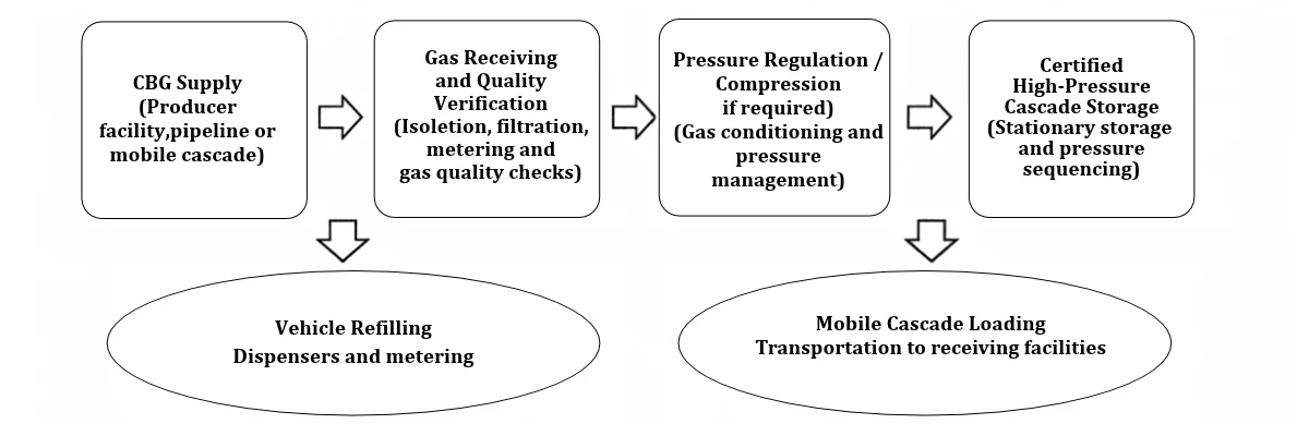
The process begins with receiving specification-compliant CBG from a producer, pipeline or mobile cascade. Gas quality and pressure are verified before conditioning or compression, where required. The gas is then directed to certified storage systems for vehicle dispensing or mobile cascade loading. The final configuration depends on supply pressure, throughput, storage requirements and the selected distribution model.
4.3 Safety Systems
Safety systems include fixed methane detectors, flame or heat detection, an emergency shutdown system that isolates supply and stops compressors, pressure relief devices set below vessel design pressure, vent stacks routed to safe locations, breakaway couplings at dispensers and loading posts, and earthing and bonding. Hazardous-area classification governs electrical equipment selection around compressors, cascades and dispensers. The classification extent depends on the equipment, ventilation and the applicable code, and is determined in the design.
4.4 Key Machinery
Equipment is selected against throughput, inlet pressure and storage pressure, as the table indicates.
| Category | Equipment | Illustrative Scale |
|---|---|---|
| Compression | Multi-stage reciprocating compressor with cooler | Sized to daily throughput |
| Storage | Certified stationary cascade with an appropriate priority or sequencing system | Number and configuration of pressure banks determined by dispensing demand, operating pressures and equipment design. |
| Transport | Cascade-mounted trailer or truck | Vendor-specific payload |
| Dispensing | CBG dispenser with mass flow meter | Single or multi-hose |
| Gas conditioning | Dryer, coalescing filter, analyser | Inlet-flow matched |
| Safety and control | Gas detectors, ESD, SCADA | Site-wide coverage |
| Electrical | Transformer, DG set, flameproof fittings | Load-study based |
4.5 Equipment Comparison for CBG Storage and Refilling Facilities
| Equipment | Available Options | Selection Considerations |
|---|---|---|
| Compressors | Reciprocating compressor; booster compressor | Inlet pressure, delivery pressure, throughput and energy consumption |
| Stationary storage | Steel-cylinder cascades; composite-cylinder cascades where approved | Storage capacity, weight, certification, footprint and lifecycle cost |
| Mobile storage | Truck-mounted cascades; trailer-mounted cascades | Payload, transport distance, vehicle limits and unloading arrangements |
| Gas conditioning | Filtration; drying systems where required | Moisture, contaminants, inlet gas quality and equipment requirements |
| Dispensing systems | Single-hose; multi-hose dispensers | Vehicle demand, simultaneous filling requirements and metering accuracy |
| Monitoring and control | Local control panels; PLC/SCADA-based systems | Automation requirements, monitoring, safety integration and operating complexity |
Equipment selection should consider gas throughput, operating pressure, storage requirements, transportation distance, energy consumption and lifecycle costs. Compressor and cascade configurations must also meet applicable safety and certification requirements. Final specifications should be established through project-specific engineering assessments and vendor evaluations.
5. Land, Plant Layout and Utility Requirements for a CBG Storage and Transportation Facility in India
Layout, utilities and hazardous-area controls determine whether the facility can operate safely and expand.
5.1 Land and Site Access
Land requirement depends on configuration. A dispensing-only daughter station occupies far less area than a mother station with compression, large stationary storage, trailer parking and loading bays. Area is derived from equipment footprint, statutory safety distances, vehicle circulation, queuing space and expansion margin, so a single acreage figure should not be assumed. Site access must allow trailer entry and turning, and the approach road must carry the loaded vehicle weight.
5.2 Layout, Equipment Spacing and Vehicle Circulation
Layout places compressors, cascades and loading posts at specified separation from the boundary, buildings, dispensers and each other, following the applicable petroleum and gas safety distances confirmed with PESO. Vehicle flow should be one-way where possible, with separate routes for retail vehicles and cascade trailers, and with trailer parking outside the dispensing area. Vent stacks are positioned for safe dispersion, and the control room is placed outside the classified zone.
5.3 Power, Ventilation and Fire Protection
Electrical supply is sized from a load study covering compressors, dispensers, lighting and controls, with standby generation for safety systems and controlled shutdown. Compressor enclosures need ventilation adequate to prevent gas accumulation. Fire protection follows the applicable fire code and PESO conditions, and typically includes extinguishers, hydrant or water-spray provisions where required, and detection linked to emergency shutdown. Requirements depend on site classification and authority review.
6. CBG Storage and Transportation Facility in India: Cost, CAPEX, OPEX and Financial Feasibility
Cost and revenue are driven by throughput, supply price, delivery distance and utilisation, so they are modelled project by project.
6.1 CAPEX Components
CAPEX covers land or lease, civil works and foundations, compressors, stationary cascades, dispensers, metering and gas conditioning, transport assets such as cascade trailers and prime movers, electrical and utilities, safety and control systems, installation and commissioning, engineering and approvals, and contingency.
The share taken by each head varies with configuration: a mother station is compressor- and cascade-heavy, whereas a daughter station is dispenser- and civil-heavy, and a transport-led model carries a large vehicle-asset component. No benchmark rupee figure is applied here; the illustrative project in Section 7 shows how heads are assembled.
6.2 OPEX and Working Capital
Operating cost comprises gas procurement, electricity for compression, transportation including fuel, driver and maintenance costs, equipment maintenance, labour, insurance, statutory testing and inspection, and administration. Gas procurement is normally the largest single item. Working capital covers gas inventory in storage and in transit, customer receivables, supplier payment cycles and operating reserves, and depends on credit terms with suppliers and customers.
6.3 Revenue Models
Revenue models include a refilling margin on dispensed gas, a transportation or delivery charge per unit of gas, a combined delivered-gas price to industrial customers, and a compression or storage service fee for third-party gas. The chosen model determines which variables dominate returns: a margin model depends on throughput and spread, whereas a logistics model depends on trailer utilisation and distance.
6.4 Project Economics
The table shows a single illustrative project: a mother-and-refilling facility with an assumed compression capacity of 4,000 kg of CBG per day, integrated stationary storage, and two cascade trailers. It is not a market benchmark.
(Figures are indicative in nature, may vary.)
| Cost Head | Basis / Assumption | Illustrative Investment (INR) |
|---|---|---|
| Land & civil works | Approx. 1.5 acres, foundations, roads | INR 3.0-4.5 crore |
| Plant & machinery | Compressors, cascades, dispensers | INR 9.0-13.0 crore |
| Utilities & installation | Power, safety systems, commissioning | INR 2.5-4.0 crore |
| Transport assets | Two cascade trailers and tractors | INR 2.0-3.5 crore |
| Engineering & pre-operative | DPR, approvals, testing | INR 1.0-1.8 crore |
| Contingency and total | Contingency on subtotal; total | INR 17.5-27.0 crore |
7. Detailed Project Report (DPR) for a CBG Storage and Transportation Facility in India
A DPR converts the concept into a bankable document, and each component below is prepared with site and supplier data rather than generic assumptions.
7.1 Executive Summary, Market and Gas Supply Assessment
The executive summary states objectives, location, business model and proposed capacity. The market assessment identifies customers, refilling and industrial demand, and competing fuels. The gas supply assessment documents supply agreements, delivered gas specification, procurement price basis, contract tenure and reliability, because supply interruption is among the largest project risks.
7.2 Technical Feasibility, Capacity and Logistics Planning
Technical feasibility defines the receiving, compression, storage, transport and dispensing configuration. Capacity planning derives daily CBG throughput, storage volume, operating hours and delivery frequency from demand. Logistics planning computes trailer payload, distance, trips per day, loading and unloading time and turnaround to fix fleet size, and flags when residual pressure at delivery limits effective payload.
7.3 Machinery, Site, Layout and Regulatory Assessment
The DPR includes the equipment schedule with specifications, site selection and layout with hazardous-area provisions, and a regulatory assessment listing PESO, PNGRB, fire and pollution-related requirements that apply to the chosen model, each flagged for confirmation with the issuing authority.
7.4 CAPEX, OPEX, Working Capital and Financial Projections
CAPEX is built up as in Section 6.4 from vendor quotations. OPEX covers gas, electricity, transport, maintenance, labour and insurance. Working capital is derived from inventory and credit terms. Financial projections present revenue, operating margin, cash flow, break-even, DSCR, NPV and IRR under base and sensitivity cases, with assumptions for price spread, utilisation and gas cost stated explicitly rather than taken from benchmarks.
7.5 Implementation Schedule and Risk Assessment
The schedule sequences engineering, approvals, procurement, installation, testing and commissioning, with approval and delivery durations treated as project-specific. The risk assessment covers supply interruption, gas losses, equipment failure, safety incidents and utilisation shortfall, each with an owner, mitigation and contingency.
8. Regulatory Approvals, Safety Compliance and Project Challenges for a CBG Storage and Transportation Facility in India
Approvals and operating risks determine whether a sound design can run at its planned throughput.
8.1 PESO Approvals
The Petroleum and Explosives Safety Organisation (PESO) administers statutory requirements for the storage, handling and transportation of compressed gases. Depending on the equipment and installation, the applicable framework may include the Gas Cylinder Rules, 2016, as amended, for gas cylinders and cylinder cascades, and the Static and Mobile Pressure Vessels (Unfired) Rules, 2016, as amended, for pressure vessels falling within their scope.
The applicable regulatory framework must be determined by the approved vessel design, construction, gas service and installation configuration. Cylinder cascades and other pressure-vessel arrangements should not automatically be assumed to fall under the same licensing category. These requirements should be confirmed with PESO before finalising the facility design and procurement.
8.2 PNGRB, Standards and Other Permissions
PNGRB requirements should be assessed according to the facility's specific activities. Pipeline injection, operation within an authorised city gas distribution network and automotive fuel dispensing may attract different regulatory and technical requirements. Standalone CBG storage and transportation should not automatically be treated as an authorised CGD activity. The applicable requirements must be confirmed with PNGRB and other relevant authorities.
8.3 Safety Standards and Operating Practice
Safety practice covers hazardous-area classification, equipment certification, periodic hydrostatic and visual testing of vessels, leak surveys, operator training, permit-to-work, emergency response plans and incident reporting. The applicable code set should be fixed at design stage and recorded in the safety case.
8.4 Common Challenges and Project Checklist
Common challenges are off-specification gas, pressure management between supply and cascades, transport economics at long distances, methane leakage, compressor downtime and supply reliability. A practical checklist: confirm gas supply terms and specification; fix business model and capacity; secure site and safety distances; complete process and equipment design; obtain PESO and related approvals; arrange fire, electrical and pollution-board permissions; qualify vendors and test equipment; commission with leak and pressure testing; and establish inspection, calibration and emergency procedures. Each item should have a named owner and closure evidence.
Conclusion
A bankable CBG storage and refilling project is built backwards from the delivered gas specification, the throughput and logistics model, and the approval pathway for the chosen configuration. Those decisions fix the compressor duty, the cascade volume, the fleet size and the safety case, and together they set the capital requirement. Treating compression, storage, transport, dispensing and compliance as one integrated design avoids the common failure of buying equipment first and discovering later that supply, pressure or permitting does not fit it.
Three priorities are critical to project viability. First, secure a reliable gas supply with clearly defined quality specifications, as both plant utilisation and operating margins depend on it. Second, determine logistics requirements based on trailer payload, transportation distance and turnaround time rather than standard fleet-size assumptions. Third, plan classification, certification and statutory approvals alongside engineering activities, confirming their applicability to the specific project. Equipment selection and facility specifications can be optimised, but these three areas require careful planning from the outset.
PURSUING A CBG STORAGE AND REFILLING FACILITY IN INDIA?
IMARC Engineering supports investors, CBG producers, gas distributors and industrial entrepreneurs with feasibility and business planning, site selection, plant layout, equipment selection, utilities planning, waste management planning, regulatory approvals, CapEx and OpEx planning and project scheduling. The advisory covers stationery and mobile cascade systems, including gas receiving, compression, storage, transport loading and dispensing, with project-specific infrastructure and commissioning planning.
→ Schedule a CBG storage and refilling scoping consultation with an IMARC specialist
Recent Post




Trusted by Industry Leaders
We partner with global enterprises and ambitious businesses across sectors to deliver operational excellence, strategic insights, and sustainable growth through integrated solutions.











Success in Their Words
Real feedback from clients across industries. Discover how our solutions delivered measurable impact and operational excellence.

I wanted to express my sincere appreciation for your efforts in handling this matter. Your dedication and commitment have been truly commendable, and it is evident that you have put in tremendous hard work and expertise into resolving the issues at hand. We are greatly interested in continuing our collaboration with you in the future, as your professionalism and reliability have made you a trusted partner. Thank you once again for your invaluable contribution. We look forward to strengthening our partnership ahead.

It has been a pleasure working with the IMARC team. The insights provided were structured, clear, and highly valuable, helping us strengthen both our technical and financial planning with confidence. We deeply appreciate the team’s professionalism, responsiveness, and attention to detail throughout the engagement. Every requirement was well understood and effectively incorporated, resulting in a comprehensive and actionable output. Overall, our experience has been excellent, and I would gladly recommend IMARC to organizations seeking a reliable research partner.

Your service is truly exceptional. Working with the IMARC team has been a seamless and professional experience. The clarity of communication, responsiveness to queries, and consistent support at every stage made the entire engagement highly efficient. The insights shared were well-structured, practical, and perfectly aligned with our requirements, helping us make informed decisions with confidence. Overall, the dedication and professionalism demonstrated by your team stand out, and I would be glad to recommend IMARC as a reliable and trustworthy research partner.

IMARC did an outstanding job in preparing our study. They were punctual, precise, and consistently responsive throughout the entire process. The team delivered all the data we required in a clear, well-organized, and highly professional format. Their strong attention to detail, combined with their ability to meet every deadline without compromising quality, truly set them apart. Overall, their reliability and commitment made them an exceptional partner for our project, and we would gladly work with them again in the future.

IMARC made the whole process incredibly easy from start to finish. Everyone I interacted with via email was polite, professional, and straightforward to deal with, always keeping their promises regarding delivery timelines and remaining consistently solutions-focused. From my very first contact, I appreciated the professionalism and support shown by the entire IMARC team. I highly recommend IMARC to anyone seeking timely, affordable, and reliable information or advice. My experience with IMARC was excellent, and I truly cannot fault any aspect of it.

I’d like to express my sincere gratitude for the excellent work you accomplished with the study. Your ability to quickly understand our requirements and deliver high-quality results under tight timelines truly reflects your expertise, exceptional work ethic, and unwavering commitment to your customer’s success. The professionalism and responsiveness you demonstrated throughout the process made a significant difference. Our entire team and company are incredibly thankful for your dedication, reliability, and support. Once again, thank you for your outstanding contribution.